Simulating a Phone Line

Line Simulator built in an old ADSL filter box

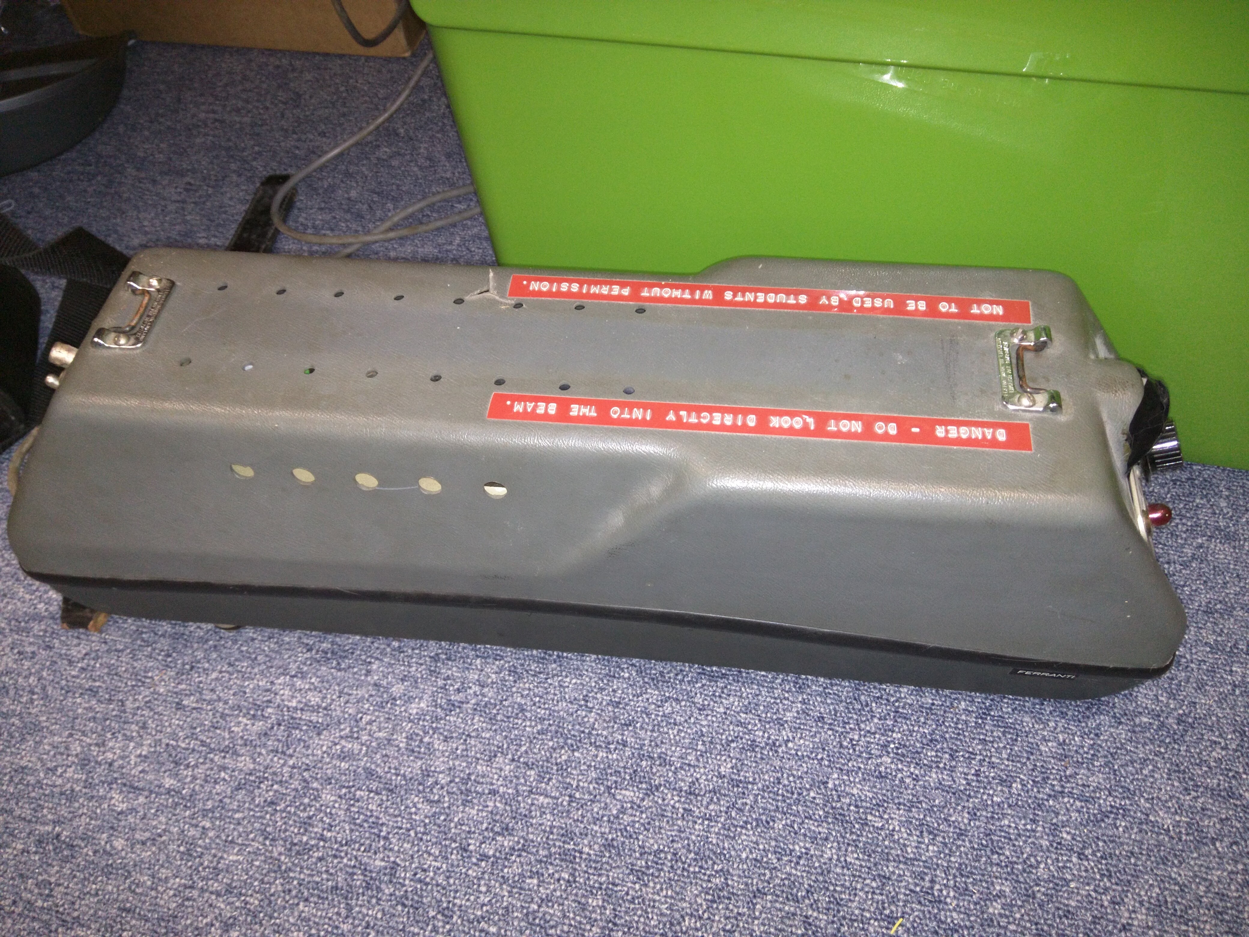
This is the second post in a multi-part series about viewdata. A few members of the hackspace are working on a project to connect a ZX Spectrum with Prism VTX 5000 modem to an emulation of a viewdata system, providing a live demonstration experience.

Viewdata connections, much like dial-up internet access which followed later, relied on audio frequency telephone communication to transfer data between the user’s terminal and the information provider they were logged into. I’ll cover details of the signal modulation in a separate article; in this article I’ll describe how I connected a real Prism VTX5000 modem to a laptop’s sound card.

A UK telephone line, like that in most countries, is a relatively simple circuit. The line is supplied from a bank of batteries with approximately 50V DC, with earth on the positive side (to prevent line corrosion by offering cathodic protection). This would have originally been supplied via a pair of relay coils, which have three main effects:

  • The coils have a DC resistance, which in practice limits the off-hook condition of the line to about 8V at 20mA
  • The coils present a large inductance, which prevents AC (i.e. the audio signal) from being lost into the supply
  • The relay contacts are used to detect when the line is off-hook

For the purposes of our simulation, we only need the line simulator circuit to behave like a line in the off-hook state. This means it can run from a low-voltage supply of 9-12V. We’re also not interested in providing a ring signal (typically around 90V AC), as it’s also not required for this project.

On a telephone line, the AC audio signal sees a resistance of around 600 ohms. Audio signals are coupled to the phone line via capacitors, which pass the audio signal but block the DC supply.

The line simulator therefore has the following requirements:

  • To provide approximately 20mA at around 8V DC with a telephone connected off-hook
  • To provide several kilohms of dynamic resistance at DC
  • To provide around 600ohms of resistance to AC
  • A means to inject an audio signal from a laptop onto the line
  • A means to take off an audio signal to feed a laptop’s line input
  • Protection to prevent overloading of the sound card

Starting with the DC requirements, a fairly simple transistor circuit can be made to act roughly like a current source, up to near the circuit’s supply voltage. Adding a bypass resistor permits the introduction of a controlled dynamic resistance at DC, and this also affects the off-hook voltage level.

To provide the required AC resistance and injection capability, the circuit can be coupled via a capacitor and series resistor to the laptop’s headphone jack. A second resistor to ground helps to block the DC supply. A headphone output has a very low resistance of a few ohms at most. A 680 ohm resistor increases this to a more suitable level. While this is slightly on the high side, it leaves some room for other parallel resistances of a few kilohms, which the circuit will introduce.

The protection and take-off requirements can be met simply by placing two signal diodes in inverse-parallel; this limits the line signal to 0.7V peak, and also limits the extent of transients when the line switches between on- and off-hook conditions.

Line Simulator Circuit Schematic

Line Simulator Circuit Schematic

The complete line simulator circuit is shown above. The LED and series resistor are used to provide suitable biasing to the transistor. An unintended side-effect is that when the phone is on-hook, the LED supply is bypassed by the transistor, so the LED also acts as an off-hook indicator.

This circuit can easily be built on a small piece of stripboard. ADSL filters are widely available, and often going spare. These provide a suitable project box and, with the rest of the filter components removed from the board, a pair of phone jacks which can be connected to the line simulator circuit. Note that the circuit as presented is not suitable for connection to a PC microphone jack as the signal level is far too high; to use this an attenuator would need to be built in, which could be achieved with a simple resistive divider.

Once constructed, check the voltage at the phone socket is about right, then plug in an old phone to check it’s working. You’ll probably hear some quiet line noise, and the LED should light when the receiver is lifted. If you connect the circuit to a laptop or music player, you should be able to hear audio played clearly through the phone, complete with that lovely tinny quality.

Viewdata – A Brief Overview

This is the first post in a multi-part series about viewdata. A few members of the hackspace are working on a project to connect a ZX Spectrum with Prism VTX 5000 modem to an emulation of a viewdata system, providing a live demonstration experience.

Back in the early ’80s, before the world wide web was a thing, there was something a little like Teletext called Viewdata.

Viewdata pages look a lot like Teletext – they share the same frame formats – and viewdata terminals likely used the same IC to produce the video signal (The Mullard SAA5050, also used in the BBC Micro for its text-only mode). While teletext pages are transmitted in the blanking interval of a TV signal, in rotation so a receiver needs to wait for the right page, viewdata operates over a telephone line and so is more interactive.

When a subscriber wanted to log onto the service, they dialed the provider they wanted to access – for example Prestel – and provided their ten-digit ID number and password to log in.

Once logged on, the user was presented with the main page, and navigated using the number keys and enter. Pages were generally arranged hierarchically, so page 1234 would be below 123, and is reached from that page by pressing ‘4’. Like Teletext, viewdata pages could consist of multiple frames, so pages longer than one frame could be constructed.

Companies who wanted to host information on a viewdata service would pay the information provider (IP); this would involve a payment for a particular length of prefix (shorter prefixes would typically be more expensive), and also per page hosted. They could edit frames using special editing software, and then uploaded these to the IP. Frames weren’t restricted to being completely passive – “submission” frames could be authored, allowing people to order goods or fill in forms. Frames could also be marked with a cost, allowing companies to collect money against a user’s account when they accessed the information.

Often, information providers would have a mailbox system, allowing users to send each other messages, which could be retrieved and read when the user logged in. Some terminals would allow these, as well as other frames, to be retrieved and stored locally, so they could be read offline without the user keeping the line open.

As well as centralised information providers, such as BT’s Prestel, software later emerged allowing people to host their own viewdata systems – often bulletin boards – or set up peer-to-peer connections. Peer-to-peer connections allowed users to phone each other, and as long as they set their modems correctly, information could be transferred half-duplex. Bulletin boards could be run on systems such as the BBC Micro, and would present themselves in the same manner as an IP.

The modem standard – v.23 – used for viewdata is asymmetric. The forward channel (download) runs at 1200 bits per second (120 characters per second taking framing into account), while the reverse channel (upload) runs at 75 bits per second (7.5 characters per second). A terminal – apart from any storage functionality – is relatively “dumb”, and transmits key presses immediately. The information provider’s system reacts as needed – whether this means sending a new frame, or echoing characters typed into a response frame. The slow reverse channel is still generally fast enough to transmit the user’s keypresses, and is fairly noise-resistant because of the low bandwidth.

There are sites which contain demonstrations of some viewdata systems – https://www.viewdata.org.uk/ is a good example of this. Follow the “Logon Now” link to access an example.

Corduroy aprons are this year’s must have hackspace accessory

I decided that I need an apron. I mostly turn up at the space in whatever I am wearing from work and sometimes things might get messy. An apron should do the trick but as it’s a hackspace I can’t just buy the first one I see. So it’s time to break out the sewing machine.

Me at the sewing machine. First off I needed a pattern or something to to copy from. Luckily Aimee already had something so I set about finding some suitable material. Traditionally these things seem to be made from something like a heavy cotton or even leather. I went for chord. Brown chord with blue trim.

Cutting out the template

I laid the pattern apron out on the big table over my cloth and after some pondering we decided to mark up a rectangle of the right length and width and just mark up the curved parts that go under the arms from the pattern. A small bit of scrap ply-wood was brought in to use as a square to get things lined up and a point of no return was passed as I made the first cut. Pinking shears are great fun, it’s like setting an alligator to work and you end up with a zig-zag cut that should not fray.

I added a centre line to help keep things lined up then chalked out the curve from the template apron. Then cut both curves in one with the sheet folded in half.

Sewing the boarders onto the materialNow for some practice runs on the machine. It’s been a while since I last had a go with this so here was some browsing of the PDF copy of the manual to see how it threads together. Then some tweaking of the tension to get it sewing right on the chord. ( I make this sound simple but I think this bit took almost the most time but I now consider myself an “expert” ) I added a plain hem along the bottom and its almost straight.

Adding the boarder.For the first attempt to attach the tape round the sides I used pins the tape in place I found that it moved about too much and the pins then made it to difficult to correct so I switched to just feeding things in an adjusting the fold as it went which worked quite well. In the end I had to unpick things quite a bit on the first run but then worked out that I needed to have a bit more tape on the front or it would work itself out.

Then finally adding on the the loop round the top and the strings round the back and it was done.

It may be a little long and I should have made the strings round the back, up the sides and around the neck from the a single piece. I also think the bit under the neck is a little to wide so it sticks out a bit but other than that I’m pretty happy with it. ( Oh and it could do with an iron, we should probably get one for the space)


Spacehack upgrades, Just in time!

You may have spotted a little while ago that we got a place at Maker Faire UK for the fourth year in a row.

For the past few years, setting up Spacehack hasn’t been a simple job, mainly because of how the server box (the gold pyramid) was a flimsy cardboard box with various things taped to it. We also had issues with the four consoles. Many LCDs were failing, pots not rotating correctly, switches not working or missing. So we had to do some upgrades.

One of the most ambitious upgrades was the server box upgrade. We wanted to get this one done before the Maker Faire this weekend, to make setup easier. I’m pleased to say that we have completed it on time! You can look forward to seeing the new server box this weekend.

The upgrades have enabled us to make the server more rugged and much more compact. We’ve eliminated the need for three of the five power supplies by making everything run on 5v. We even have a touch-screen GUI for managing the game. The GUI’s written in pascal, of course. 🙂

Just to be clear about why this needed doing; see this picture of the guts of the original server box. Yuk!

Need to etch PCBs? We can help!

Nat needed a PCB recently, so we decided to see if we could make good use of the PCB etching equipment we have in the hackspace. It’s a fairly simple process, print a positive on some laser-printer-acetate, stick it to a pre-sensitised PCB, expose it to UV, dip it in developer, then dip it in etchant.

The UV exposure box

The UV exposure box

At least, we thought it was that simple. We had a couple of failed attempts before we got a good board. We couldn’t agree on the correct time for exposure and development. On our third attempt, with two minutes in the light box and about thirty seconds in the developer solution, we got a decent image.

The first two attempts

The first two attempts

Now we really should have rubber gloves for this next bit, but we couldn’t find any. Fortunately we did have a pair of thick plastic carrier bags for handling the etching chemicals.

After allowing plenty of time in the etchant, agitating it for extra speed, we finally got a good looking PCB out.

Some of the tracks needed a little bit of fixing up afterwards, but this was just a quick test board. If this works, there will be two more done properly.

Now that we know how best to use the kit we have, if you have a project that requires a home-made PCB then why not come along and let us lend a hand?

The Long-Awaited Low-Temperature Tuck Shop.

After having this lovely glass-sided fridge in the hackspace for many weeks, we’ve finally got it to a working state.

We got the fridge for free, in mostly working condition. It really needed a clean and the fan motor was very noisy. It also had a fluorescent light bulb in the top, which wasn’t working. We tried fixing the fan, but couldn’t get it quiet-enough to prevent it being a nuisance to people working in the hackspace. In the end we decided to replace the fan with an old PC cooling fan that was much quieter.

While we had the thing open, we decided to do something about the lighting. We removed the old light bulb and instead fitted some much lower power LED strips inside the fridge. Nick did a great job of wiring these up to the switch for the old light and even added a little microswitch to detect the door opening and turn on the white lights to make it a little easier to see. (As pretty as the blue and red lights are, they’re not ideal for reading labels on things.)

Let us know what we should stock!


We’ll be back at Maker Faire UK this year

Despite crashing the USS guppy into the Life Science Centre’s unique exhibition space numerous times, somehow we’ve been invited back for the next Maker Faire UK.

This will be the fourth year that we’ve been at the Maker Faire UK. We will, of course, be taking spacehack. We’ll also be bringing along some other projects too. John’s tetris table shall be making an appearance and we’ll no doubt have some other goodies you can play around with.

Be sure to check out http://www.makerfaireuk.com/ when details of who else is exhibiting are released.

Some photos of our past adventures in the Life Science Centre…

York Hackspace at MakerFaire UK 2014

Another random selection of interesting things

It’s just another week at the hackspace, here’s a few thing that were going on last Wednesday.

We recently had a generous donation of some old tech, it included this intriguing Ferranti Laser. Nat had a go switching it on, it seems to do something, we’re just not sure what it’s purpose is. If anyone knows, help us out by letting us know how to use it. (We’re already fairly sure it’s not powerful enough be used to make a laser cutter.)

Another fabulous little relic included in the donation was this this Vest Pocket Kodak. If anyone has any film that will work with it, come along next Wednesday and try taking a picture! We’d love to see the results.

In other news; Dave found something to do with some of the used bottle caps that are awaiting recycling.

And Bob modernised a ZX81 with a composite mod kit. So there’s even more retro projects going on in the space. No luck with the ZX printer as of yet, but perhaps with some tinkering it could rival the other sinclair-computer-printer project by being even more retro.

It’s good to have places to put things

After much discussion, we finally decided what we needed to do to make better use of the space we have. We haven’t quite got it all done, but we’re most of the way there, so we decided to share some photos of how it’s going.

What we wanted was a shelf above the electronics workbench so that we could put all of the test equipment on the shelf so that it leaves the workspace below free. Most of the wood we used came from old pallets, the shelf is one large plywood sheet that was otherwise going to end up in a skip. In addition to the large shelf, we have most of what we need to in place for some extra smaller shelves above.

Of course this shelf is going to cast a shadow onto the desk, but with an abundance of white LED strips in the hackspace, it’s just a matter of time before somebody sticks one to the bottom of the shelf.

We’ve also addressed the issue of the overflowing bookshelf and cupboard. They now have a friend in the form of a black plastic shelf unit.

1 2 3 4 5 6